📻Build a Real-Time Mission of 2.4 GHz
2.4 GHz Real-Time Mission.
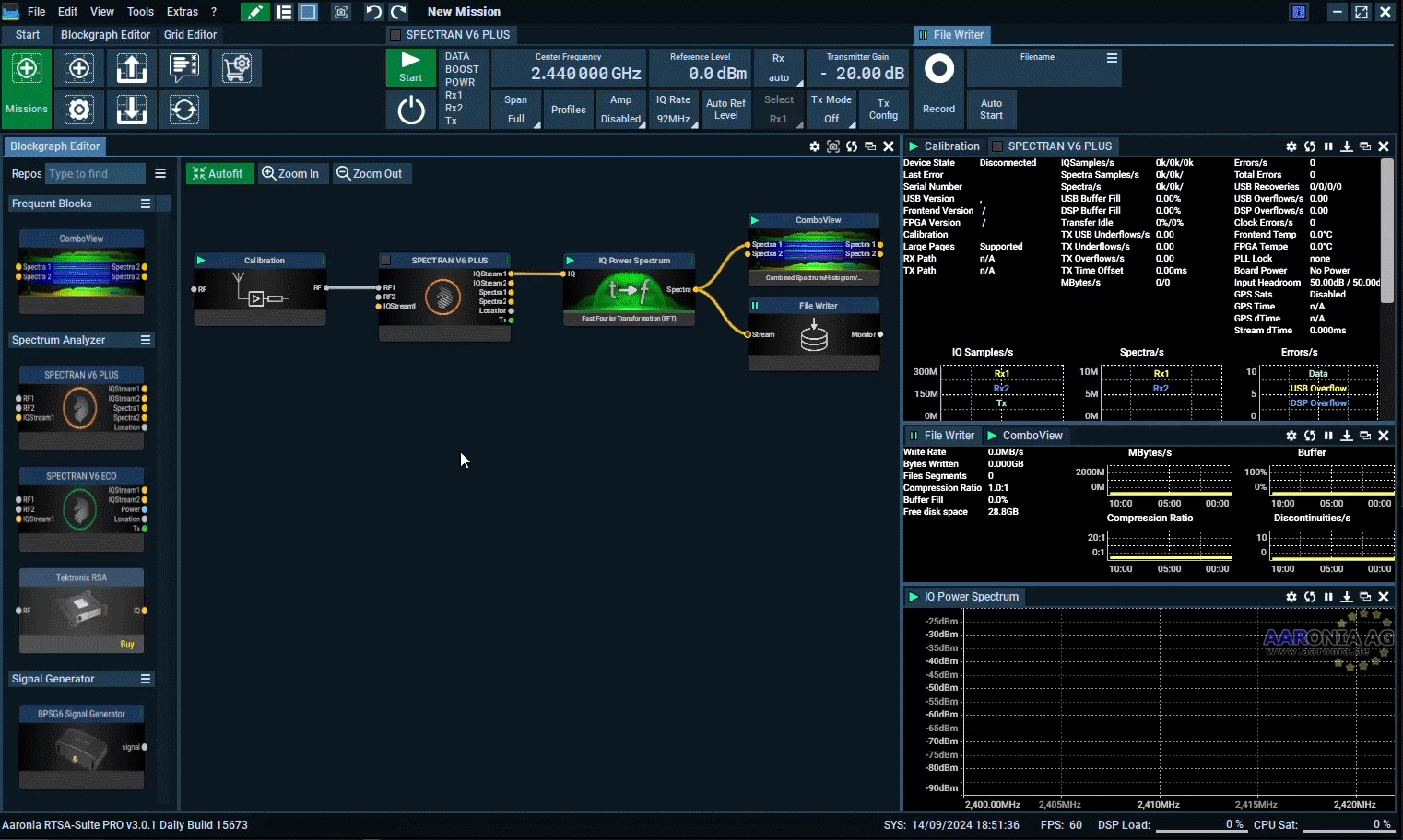
In this lab, you will build your first real-time mission using Aaronia RTSA-Suite Pro. The mission is already available as a Factory Mission, but if you want to build one yourselves follow this guide.
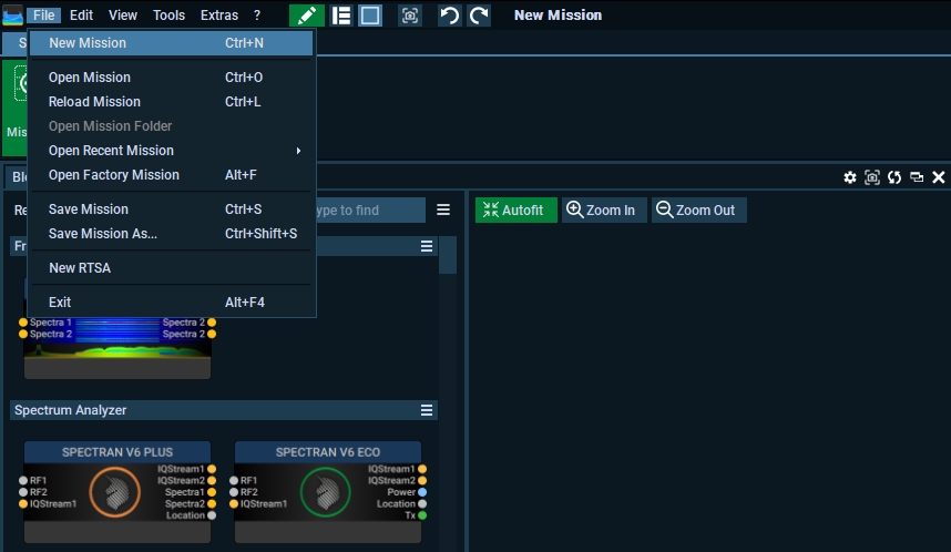
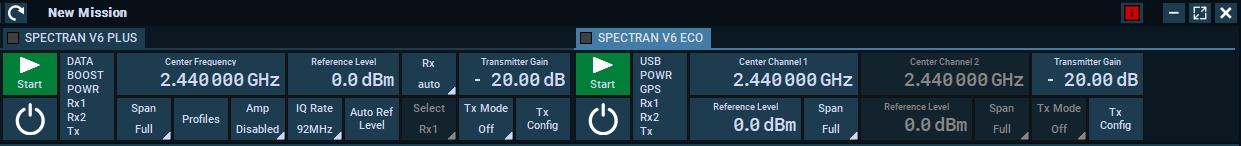
Step 1. New Mission
Open a new mission, by going to the File menu -> New Mission or press CTRL+N
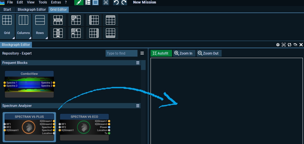
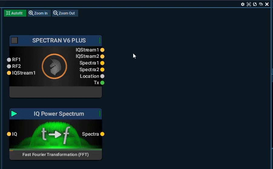
Step 2. Add the Spectran V6 block
Drag the Spectran V6 Plus or Spectran V6 Eco block to the blockgraph editor window the the right.
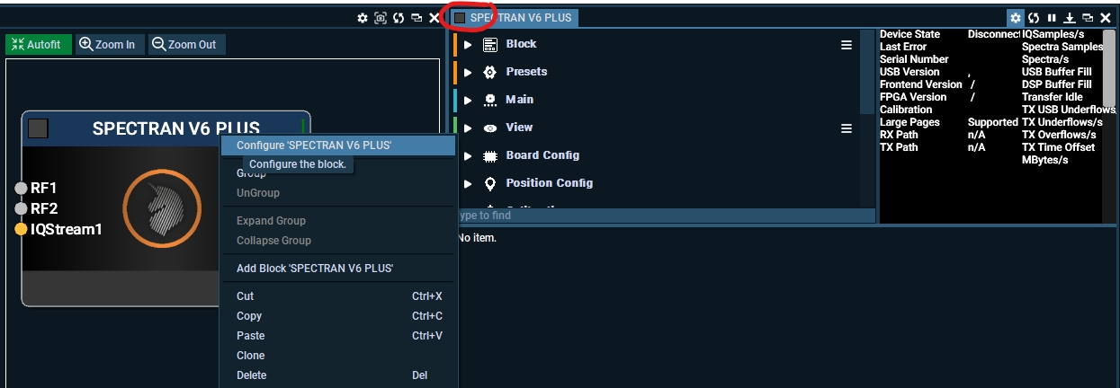
When the block is added, open up the settings for the block by right-clicking the block and press Configure, or double tap the the "Spectran V6 Plus inside the mission window.
There are a lot of setting inside this block, and most is covered herehttps://v6-forum.aaronia.de/forum/topic/spectran-v6-block/ and https://v6-forum.aaronia.de/forum/topic/spectran-v6-eco/.
You can for example turn on the V6 Plus to Low Power Mode (disable the Tx and FFT streamings (Spectra1 & Spectra2)), turn on Fan Control so the fan will not run at 100% fan speed all the time, save all your setting as a template and many other settings that you can also find in the top menu.
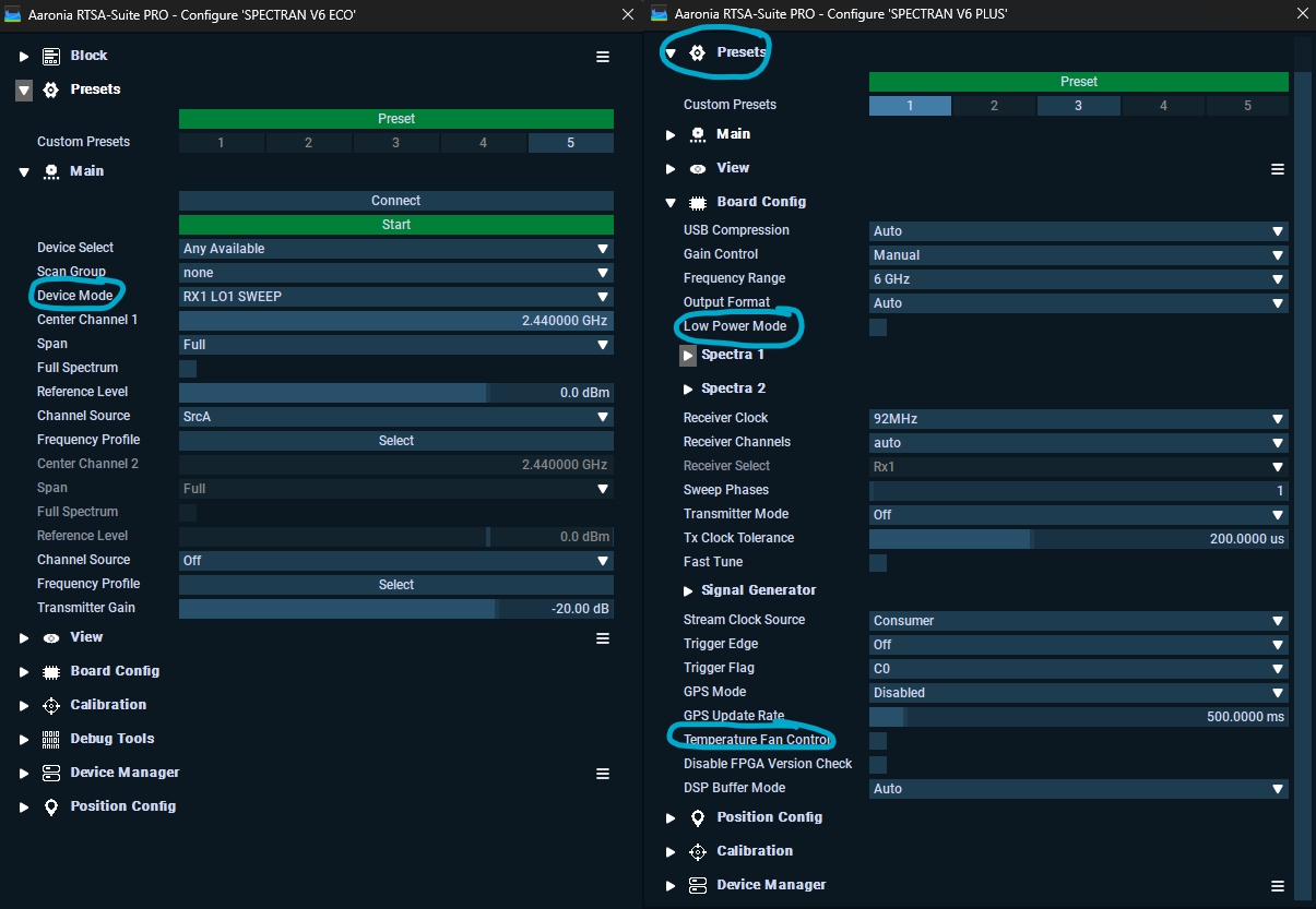
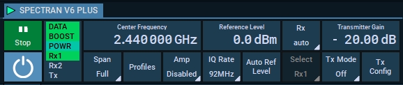
The most important settings that you would need you will find in the top menu after you added the block. Here you set the Center Frequency, Reference Level etc above from your mission.
V6 Block Input and outputs
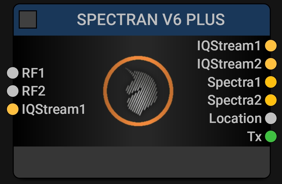
Left hand side inputs:
RF1 (RF input #1)
RF2 (RF Input #2)
IQStream1 (IQ data for Tx)
Right hand side outputs:
IQStream1 (IQ data from Rx1)
We will mostly use the IQStream1 output in this guide
IQStream2 (IQ data from Rx2)
Spectra1 (SPECTRA data from Rx1
Spectra2 (SPECTRA data from Rx2)
Location (GPS data from internal GPS receiver)
Tx (Meta data from Tx)
Source: https://v6-forum.aaronia.de/forum/topic/spectran-v6-block/
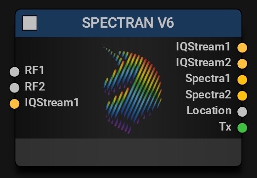
Left hand side inputs:
RF1 (RF input #1)
RF2 (RF Input #2)
IQStream1 (IQ data for Tx)
Right hand side outputs:
IQStream1 (IQ data from Rx1)
IQStream2 (IQ data from Rx2)
Power (Power meter data)
Location (GPS data from internal GPS receiver)
Tx (Meta data from Tx)
Source: https://v6-forum.aaronia.de/forum/topic/spectran-v6-eco/
Step 3. Add the IQ Power Spectrum Block
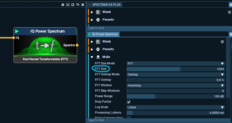
This block converts IQ data (raw real-time data) using FFT into Spectra data, the base license has a 32K FFT feature but this can be upgraded around 1M FFT.
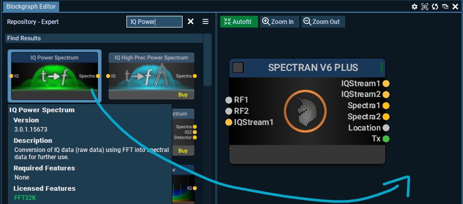
Drag the blocks together like this and connect it from IQStream1 output to IQ input.
You can just drag the block and drop in over another block, and they will connect automatically!
This will send I/Q data to the I/Q Power Spectrum block, where your CPU performs the FFT calculations, and data is loaded into RAM first, so it is important with two DDR4 or DDR5 sticks to enable dual-channel.
Depending on your computer’s performance, you may need to adjust the FFT size. A larger FFT size demands more computing power. The standard setting is 1024, but with the standard license, it can go up to 32K.
You can also set the FFT Size Mode to options like RBW (Resolution Bandwidth) or bins. In this mode, the number of FFT points corresponds to the number of bins, with the width of each bin determined by the RBW. As a result, changing either the FFT size or the RBW will automatically adjust the other, since they are interrelated.
Read about the block in more details here: https://v6-forum.aaronia.de/forum/topic/iq-power-spectrum/
Read about FFT Window, and what to use here: https://v6-forum.aaronia.de/forum/topic/different-fft-windowing-types-how-to-use-example-screenshots/
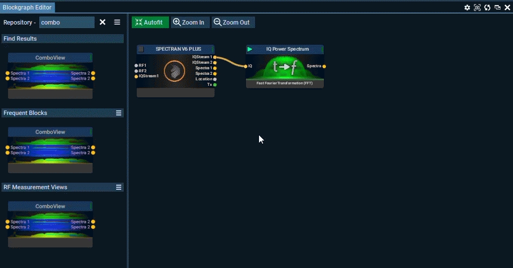
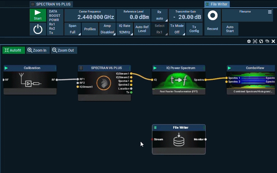
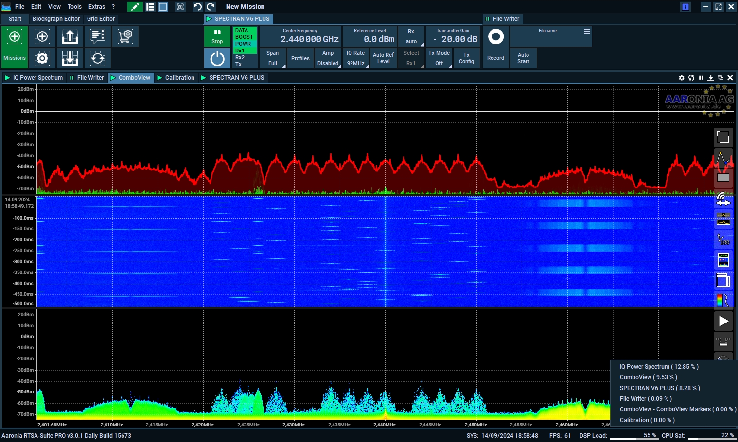
Step 4. Add Spectrum View block (Combo Block)
In this lab, we will do it a bit different than the Factory Mission and use the ComboView Block that can display spectrum, histogram and waterfall in one block. Where each of them can be paused, removed all in one single block.
Find the block in the block repository on the left, and add the block to your mission and drag a line from from the IQ Power Spectrum to the Specta Input on the ComboView.
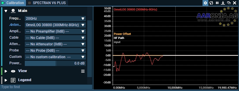
Step 5 (Optional). Add the calibration block
The Calibration block offers full control over all loss and gain from connected loads to the Rx inputs, making it highly useful for precise data measurements. For more information on this block, visit Calibration Block.
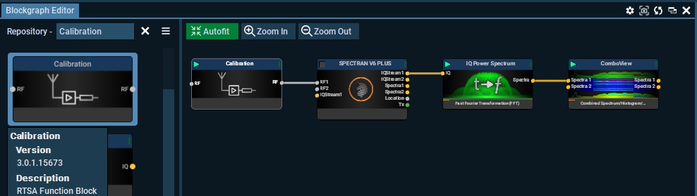
For example, if you're using the OmniLOG Pro 30800 from Aaronia, the complete gain diagram will be available in the Calibration block. When added, the Spectrum View will apply the antenna’s loss and gain, providing more accurate measurement data.
Step 6 (Optional). File Writer
You can record the IQ data, or the Spectra data with the File Writer Block. When you record IQ data you will be able to decode the data later, but the file sizes will be bigger, with Spectra you end up recording data that is already converted using FFT and you will not be able to decode any data later with the file.
GIF below shows how to connect, with IQ you would need to connect it before the IQ Power Spectrum block, and for Spectra you need to connect it to the Spectra Output on the Power Spectrum Block.
Step 7. Fix the mission view
I guess now, the mission looks quite messy, and you would like to have the blocks placed in a different order, this is best to show in yet another gif. RTSA-Suite Pro is nothing like us Wi-Fi people are used to, maybe Cisco Spectrum Expert has some similarties where you can move and place different views like you can do in RTSA-Suite Pro.
Step 8. Start your mission
Rember to use a RF/SMA Limiter before you start any mission
Now, let’s begin the mission. Turn on your V6 and press Play (just pressing Play will also turn it on)
It might not look impressive right away, but don’t worry—we’ll make it look great on the next page.
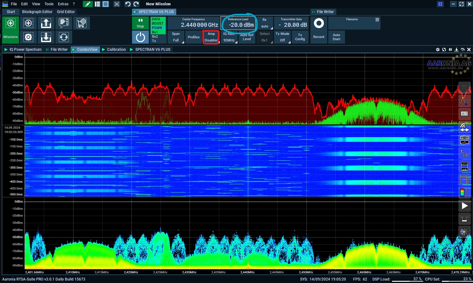
Step 9. Change the reference level
The reference level can be changed from the top-view, the lowest possible setting without enabling any amp or preamp is at 0dBm, but it will boot up at -20dBm as this is recommended since this will not have any amplifiers enabled.
Next up, Colors and more settings
Last updated
Was this helpful?